Heat Exchanger Advice Tool

Four steps to identify the heat exchanger technology suited to your process and estimate its performances, budget and lead time.

  1. Step 1Criteria
  2. Step 2Technology
  3. Step 3Process data
  4. Step 4Balance sheet

What are the criteria driving your process? Out of 10 criteria, indicate your top 3

Click the criteria in your order of preference; click a selected criterion to remove it. The “i” button gives details on each criterion.

No. 1 Choose a criterion
No. 2 Choose a criterion
No. 3 Choose a criterion

The 6 technologies assessed

Click a technology to read its description.

Efficiency

Heat exchanger efficiency is related to its heat exchange area ability to cause turbulent flows allowing high flux transfer at the wall.

Flowing in a channel causes frictional forces which will result in the creation of a dynamic boundary layer at the wall where the fluid is at practically zero speed. The phenomenon limiting heat transfer is in fact a conduction through this dynamic boundary layer. Such effective geometries make it possible to reduce the thickness of this layer and therefore the thermal resistance by conduction.

The circular channel (smooth tube) requires very high Reynolds numbers (hence speeds) (10000) to achieve turbulent regimes. Thus, there is a Gauss curve velocity profile with a maximum centre velocity and a rather thick boundary layer.

The rectangular channel with low inter-plate spacing allows, thanks to edges effects to disturb this layer and the turbulent regime is obtained from Reynolds number of 1500 with a flat speed profile.

The more efficient plate heat exchangers geometries will result in turbulent flow regimes for Reynolds from 150 to 300. The plates are generally pressed in order to obtain chevrons pattern (waves spread over the whole plate) at variables angles and steps.

The more turbulent the flow, the higher the film coefficient. One speaks about film coefficient intensification. Referring to smooth tube, the intensification for a rectangular channel on a WPHEBOX or SPIRAL exchanger will be 1.5 to 3, for a WPHEBLOC or PSHE exchanger of 3 to 5 and for a PHE exchanger of 4 at 8.

Compactness

The compactness of a technology generally drive the equipment choice. On one hand there may be constraints of installation and on the other hand the creation of new frameworks can heavily penalize the CAPEX.

Each technology has a specific compactness related to the cross sections which are implemented on each circuit. For example, it is possible to stack 400 square sheets of 1 meter, 0.5 mm thick spaced 2 mm in a cubic meter. It will have developed 400 m2 / m3.

Generally, the technologies offering the most important compactness are also those that provide the greatest turbulence and therefore the best exchange coefficients. Thus, for a water/water exchanger, traditional plate and frame heat exchanger will easily get a product coefficient U per compactness of 6000 W / m 2x 400 m2/m3. Shell and tub heat exchanger will only reach a product 2500 W / m2 ° C x 50 m2 /. As a conclusion, for 1 m3 required in PHE, S&T will require 19 m3 (ratio 6000x400 / 2500x50).

Even if these ratios are to be moderated by the installation and connection requirements of each technology (the PHE heat exchangers are equipped with mounting frames with rear legs and lower and upper guide bars for mounting and maintenance), one can easily understand the advantage of plate solutions often referred to as compact exchangers.

Fluid with particles

As heat exchangers operation is concerned, there is often a confusion between the channel plugging risks and fouling of the heat exchange area.

Most manufacturers recommend the installation of filters in their maintenance instructions in order to collect the particles in suspension (particles with diameters less than 0.5 mm). When the fluids contain particles, the installation must be stopped too frequently to clean the filter unless two filters in parallel are installed. In both cases, the cost of installation and operating costs (CAPEX-OPEX) are increased.

In many cases, this plugging risk does not mean necessarily performance reduction by walls fouling. The fouling can be a complex phenomenon, it results in the creation of a film on the wall opposing resistance to heat transfer. Users will therefore benefit from moving towards solutions that will favour wide gap channels to avoid clogging.

The S & T solution with tubes of large diameter remains the best known particularly in the food industry (pasteurization of pulp) or in the environment (fermentation sludge treatment). Unfortunately, it often leads to very bulky installations and high costs.

The Spiral heat exchanger thanks to the uniqueness of its channel, offering 40 mm free gap channels and counter-current flow will allow to obtain high efficiencies. One can expect significant downsizing the equipment and as a result the investment . It exists in such heat exchanger channels a self-cleaning phenomenon due, on one hand, to the centrifugal force which projects the particles throughout the spiral flow from the centre to the periphery but also because the deposition of particles causes locally a decrease in the cross-section of the channel until re-entrainment of the deposits under the effect speed increase.

There are also wide-plate plate exchanger solutions.

Very fouling fluids

Six different types of fouling can be differentiated at the wall: particulate fouling, biological, by chemical reaction, solidification, scaling or corrosion.

Physicochemical phenomena are not necessarily related to the technology whereas the deposition of fine particles in the dynamic boundary layer (see effectiveness) will be influenced by the types of flow. Thus, unlike the risk of clogging, the ideal geometries will be those which make it possible to obtain high turbulence. The capacity to keep away from fouling is characterized by the shear stress at the wall, the higher it is, the less the dynamic layer develops, the less the particles settle down. Engineering often requires sizing of equipment to obtain stress values ranging from 15 to 50 Pa. Only plate heat exchangers can then be used.

Despite the capacity to limit the fouling of certain technologies, it will sometimes be necessary to choose technology offering real access possibilities for mechanical cleaning, either by disassembling the plate pack (PHE) or by openings the distribution boxes (WPHEBOX ).

It is also strongly advised to carry out chemical preventive cleaning, an increase of the pressure drop of 30% must generally make it possible to trigger such an operation.

Fouling often changes over time to a maximum value (asymptotic curve). The engineering recommends to design the heat exchangers taking into account a resistance value for fouling insuring performances of the exchanger even fouled. There are some reference works which give usual fouling values (T.E.MA.). However, we must remain very attentive to the result of such design. Indeed, these fouling coefficients result in a reserve of exchange surface. This overdesign can then prove detrimental to the operation of the exchanger. Since the set temperatures are too quickly reached when the unit is clean, the control valves will then impose either low cooling water flow rates and therefore high wall temperatures, which will cause scaling or a drop in the Steam pressure of the heaters, with the risk of malfunctioning Traps and water hammer. Care should be taken to avoid surface excesses greater than 50%, most of engineering company now recommend values of 15 to 30%.

Extension capacity

Investments are often made with plant growing capacity over several years. This translates into a need for progressive capacity on the exchangers.

Size the equipment with the forecasted max. flowrate is rarely the right solution. In fact, at commissioning, the velocity in the exchanger will be too low. This can result in lack of performance due to laminar flow (obtained at low Reynolds number see "efficiency") or accelerate the fouling.

When possible, several exchangers should be installed in parallel and put into operation as the capacity increases, but this is a major disadvantage for CAPEX.

One can also play on the temperature levels of the utility fluids (use warmer cooling water or a steam at lower pressure), whereas the OPEX can then be penalized.

When the operating conditions permit (temperature pressure), the plate and frame heat exchanger (PHE) provide an extremely efficient and economical solution. The heat exchanger is then sized with the initial capacities and the frame will be defined as to receive more plates later to ensure full operation.

This extension is also welcomes when engineers are driving revamping project.

Repair possibility

The operating conditions of the equipment often cause breakage by fatigue or corrosion. There are also malfunctions in installations generating circulation defects in the exchangers, vibrations or water hammer.

Access to the unit is then required for inspection and repair.

The Shell and tube heat exchanger, if equipped with removable boxes (BEM, AEL or NEN for example), will allow the localization of leaking tube during hydraulic test. It is then possible to plug the tube. It is sometimes asked to do the thermal sizing for run with 15% of plugged tubes. This makes it possible to avoid production losses, the "re-tubing" of the unit will be done during the annual shutdowns.

Plate and Frame HE (PHE) also offer the possibility to remove easily leaking plates. Their location on the other hand is more delicate. It is necessary to dismantle the plate pack, clean the plates and perform a dye penetrant test (except when leak can be seen at gasket decompression zones). It is recommended to have a stock of spare plates and gaskets even though manufacturers can usually provide these parts in very short lead-times.

The welded plate heat exchangers WPHE or Spiral heat exchanger SHE are more difficults to repair. They require either in-depth training of site maintenance specialists or dispatch of equipment to the manufacturer facilities, since on-site intervention is very rarely possible.

However, it is sometimes possible to plug a channel on a WPHEBOX or WPHEBLOC welded plate exchanger. However, the loss of capacity will be greater than on a tubular exchanger.

Pressure

SHEPHEWPHE BLOCWPHE BOXS&TPSHE
Bar302032451000100

Temperature

SHEPHEWPHE BLOCWPHE BOXS&TPSHE
°C450180350350750350

Flowrate

SHEPHEWPHE BLOCWPHE BOXS&TPSHE
m3/h750500040007500100004000

Area

SHEPHEWPHE BLOCWPHE BOXS&TPSHE
m25004000850150025001500

PHE

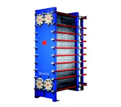
Plate and frame heat exchanger PHE

Plate and and frame heat exchanger PHE

Plates with perimeter gaskets are pressed together by two pressure plate, very flexible, high turbulence thanks to herringbone pattern which improve efficiency, complete range of plate models from 0,1 to4 m2 available with DN25 to DN500 connections

Mechanical cleaning by frame opening, gasket replacement required

Stainless steel, 254SMO, Titanium

Up to 20 bar / 180°C, Up to 4000 m2/unit, 400 m2/m3, max flowrate 5000 m3/h

High efficiency, capacity extension by adding plates

PSHE

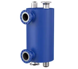
Welded plate and shell heat exchanger PSHE

Welded plate an shell heat exchanger PSHE

Circular welded plate, chevron design assembled in to a cylindrical shell, the famous plate efficiency combined to the shell and tube robustness, can be offered with extractible plate pack

Very difficult cleaning, nearly impossible

Stainless steel, 254SMO, Titanium, Nickel alloy

Up to 100 bar / 350°C, Up to 1500 m2/unit, 300 m2/m3, max flowrate 4000 m3/h

Very good efficiency

WPHE BLOC

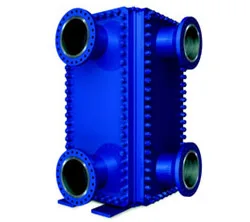
Welded plate heat exchanger WPHE BLOC

Welded plate heat exchanger WPHE BLOC

Square plates with generally chevron plates, welded together to form a plate pack fitted in a cubic frame equipped with four side panels for access on both channels

Cleaning by panels opening

Stainless steel, 254SMO, Titanium, Nickel alloy

Up to 32 bar / 350°C, up to 850 m2/unit, 150 m2/m3, max flowrate 4000 m3/h

Very good efficiency

WPHE BOX

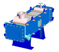
Welded plate heat exchanger WPHE BOX

Welded plate heat exchanger WPHE BOX

One pressure self resistant dimpled plate channel, one free gap channel, up to 40 mm gap, plates pairs are welded together to form a plate pack with rectangular distribution box at each ends, two pressure plate tightened by bolting secure pressure withstanding, the unique rectangular free gap channel

Easy mechanical cleaning on one side, access possible on the other

Stainless steel, Nickel alloy

Up to 45 bar / 350°C, Up to 1500 m2/unit, 100 m2/m3, max flowrate 7500 m3/h

Good efficiency

SHE

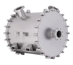
Spiral heat exchanger SHE

SPIRAL heat exchanger SHE

Nonesuch design, two single channels from 5 to 70 mm which are winded together around a tubular centre, pressurised into a cylindrical shell, ideally suitable for fluids with particles, centrifugal force create self cleaning

Mechanical cleaning by cover opening

Carbon and stainless steel, Nickel alloy, Titanium

Up to 30 bar / 450°C, up to 500 m2/unit, 75 m2/m3, max flowrate 750 m3/h

Good efficiency, pure counter current

S&T

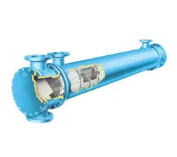
Shell and tube heat exchanger S&T

Shell and tube heat exchanger S&T

One fluid flows inside a tube bundle, the other outside the tube, into a containing shell through baffling, fully described in numerous code, fabrication rules according to T.E.M.A., third party soft for mechanical and thermal design available, easy repair on site, suitable for kettle or thermosyphon reboilers

Easy mechanical cleaning on tube side, possible on shell side by extracting the bundle (TEMA BEU design )

Carbon steel, stainless steel, refractory alloy, 254SMO, Titanium, Nickel alloy, Monel.

Up to 1000 bar / 750°C, up to 2500 m2/unit 50 m2/m3, max flowrate 10000 m3/h

Poor efficiency

Fluid families

Water
–
Organic
solvent, thermal oil, alcohols, light hydrocarbons...
(thermal conductivity 0,1 to 0,2 W/m.°K)
Watery viscous
glycols, sludge
(viscosity > 5 mPa.s, thermal conductivity > 0,5 W/m.°K)
Organic viscous
silicone oils, heavy hydrocarbons...
(viscosity > 5 mPa.s, thermal conductivity 0,1 to 0,2 W/m.°K)